


A practical wire harness DFM checklist should confirm more than electrical continuity. It should show whether the harness can be stripped, crimped, routed, sealed, labeled, assembled, and tested consistently. Reviewing these details before sampling helps prevent loose crimps, blocked connectors, damaged insulation, water ingress, and fixture changes.

What a Wire Harness DFM Checklist Must Confirm
A useful review connects the drawing with the real manufacturing process. Check the wire construction, strip lengths, terminal and connector geometry, branch layout, bend conditions, sealing features, identification method, and test access. Remove avoidable variation while preserving application requirements.
Wire and Strip Length Design
Risk: A strip length that is too short may leave insufficient conductor inside the contact barrel. A strip length that is too long may expose copper, reduce insulation support, or allow strands to escape from the crimp zone.
Common design error: The wire gauge and terminal are selected correctly, but the drawing uses a generic strip length. The operator then has to correct the length by eye, which can create crimp variation and broken strands.
Design recommendation: Define strip length from the terminal specification, conductor construction, insulation diameter, and crimp tooling. Confirm the result with a first article and inspect the conductor brush, insulation position, crimp height, and pull force before releasing the design.
Terminal and Crimping Space
Risk: A terminal may match the conductor electrically but still be difficult to crimp because the tool cannot approach the terminal at a stable angle.
Common design error: The harness is designed around the finished connector outline, while the space needed for the applicator, hand tool, inspection gauge, or rework access is ignored.
Design recommendation: Review the terminal, wire gauge, crimp direction, tooling access, and inspection position together. Leave enough room for repeatable operation instead of relying on manual correction. This is especially important for small-pitch terminal wires, where a 1.25 mm or 1.5 mm interface may require more controlled positioning than a larger terminal.
Connector Selection and Assembly Clearance
Risk: An unsuitable connector can create reversed connections, blocked locks, incomplete insertion, or difficult maintenance even when the electrical pinout is correct.
Common design error: The connector fits in the CAD model but the operator cannot reach the latch after nearby components, covers, or cable bundles are installed.
Design recommendation: Confirm pin count, keying, latch position, mating direction, insertion space, removal space, and access to the actual mating connector. A 2.54 mm connector may suit standard module interfaces, while a 2.0 mm connector can be more suitable where internal space is limited. Select by interface and assembly conditions, not by pitch alone.
Branch Layout and Breakout Design
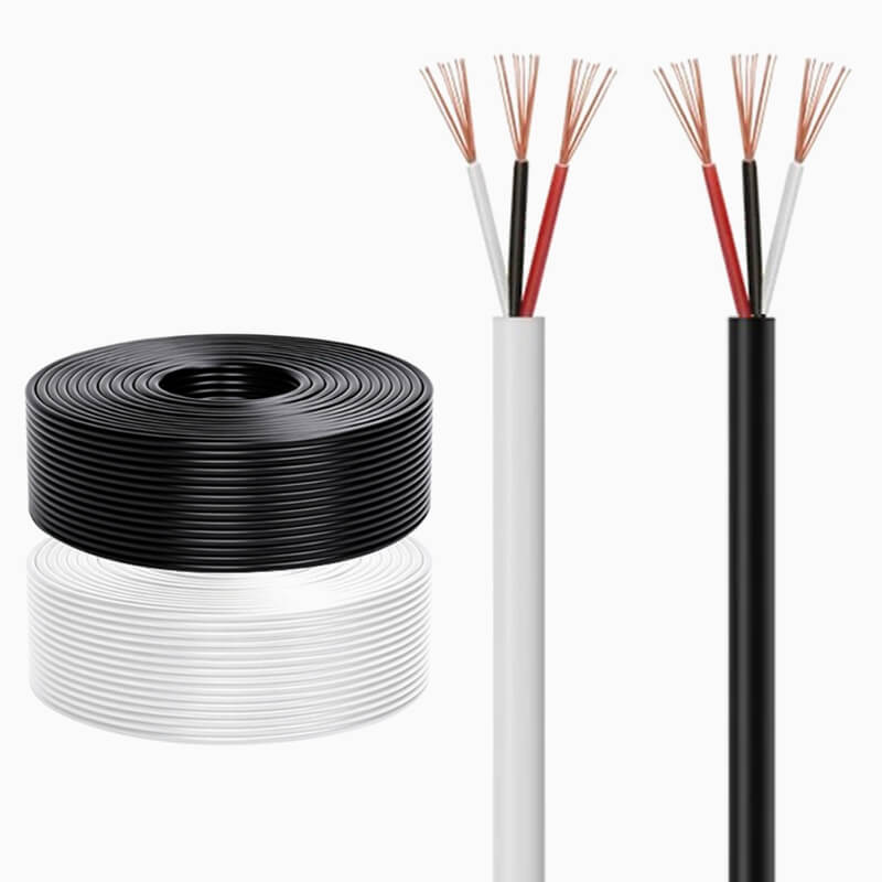
Risk: Poor branch angles, short breakouts, and crossing wires make the harness difficult to lay out on a board or fixture.
Common design error: The schematic is correct, but several branches leave the trunk in conflicting directions. The finished harness then twists, pulls against the terminals, or requires manual rearrangement.
Design recommendation: Review branch direction in the installed position and on the assembly board. Keep the main trunk, branch points, fixing points, and connector exits aligned with the actual route. Avoid forcing a short branch to make a sharp turn immediately behind a terminal.
Minimum Bend Radius Control
Risk: Bending a cable too tightly can crack the insulation, fatigue the conductor, or concentrate stress at the connector root. Vibration makes the problem worse.
Common design error: A harness is routed around a compact enclosure with a sharp bend directly at the terminal or overmold. It passes an initial continuity test but fails after repeated movement.
Design recommendation: Separate fixed-installation and moving-installation conditions. As a reference for selected cable constructions, the product range uses approximately four times the cable diameter for fixed routing and fifteen times the diameter for moving routing. Confirm the applicable value for the chosen cable, and add strain relief where the harness exits a connector.
Sealing and Protection for Waterproof Harnesses
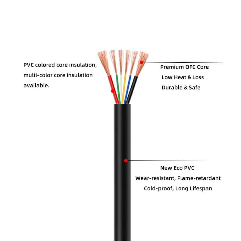
Risk: A sealing ring can be pinched, under-compressed, contaminated, or blocked by insufficient assembly space. The result may be water ingress and electrical failure.
Common design error: The drawing specifies a waterproof connector but does not show the sealing ring position, locking sequence, drainage path, or inspection access.
Design recommendation: Define the seal location, mating surface, compression condition, locking method, and target protection level. M8 and M12 waterproof cable assemblies are useful examples: threaded locking, molded construction, and sealing rings must work as one system. The design review should also confirm whether the connector will face splash, washdown, temporary immersion, or continuous moisture exposure.
Label and Circuit Identification Design
Risk: A label can be technically present but functionally useless if it is hidden, hard to scan, easily worn away, or installed in the wrong direction.
Common design error: The label location is chosen before the final branch geometry is fixed. After assembly, another cable or protective sleeve covers the circuit identifier.
Design recommendation: Specify label size, reading direction, attachment position, print durability, and batch information. Check the label after the harness is installed, not only when it is laid flat on the workbench. Identification should support assembly, service, and traceability without creating a new interference point.
Test Fixture Compatibility
Risk: A finished harness may be electrically sound but impossible to test efficiently because probes cannot reach the terminals or the fixture cannot hold the connector securely.
Common design error: Continuity and short-circuit testing are considered after the harness drawing is frozen. The test team then has to modify the fixture or test through an unreliable temporary connection.
Design recommendation: Review test points, pin definitions, connector access, fixture clearance, and the sequence for continuity, insulation, and withstand-voltage checks before production. The test method should match the product risk. A simple internal cable may need focused continuity testing, while a sealed industrial assembly may also require attention to terminal retention, insulation, sealing, and routing.
Turn the Checklist into a Pre–Production Review
The eight checks become useful when connected to a release process. Start with the drawing, BOM, connector samples, mating parts, and installation environment. Record risks, make changes, and build a first article against assembly and test conditions.
A release sequence is drawing review, DFM review, first-article assembly, electrical testing, mechanical inspection, fixture confirmation, and final drawing approval.
Industrial DC Power Cable Case: Applying DFM Under Pressure
A related Huajunxin industrial DC power cable project shows how the same design logic works under demanding conditions. The customer operated automation equipment in a 50°C to 60°C workshop with variable-frequency-drive interference. The previous cable had suffered high-temperature insulation aging and unstable power delivery, while a new production line required delivery within fifteen days.
The solution combined 150°C silicone insulation, oxygen-free copper conductors with purity of at least 99.99%, aluminum foil plus tinned copper braid shielding, a customized DC025 connector, 5A rated current, a standardized 2.5 m length, and secondary injection at the connector root. The sample was completed and tested in three days, followed by production of 10,000 pieces in seven days.
After installation, reported equipment downtime caused by cable faults fell from more than eight hours per month to less than 0.5 hours. Servo positioning deviation improved from ±0.1 mm to ±0.03 mm, and the cable service life exceeded five years. Although this was a DC power cable project rather than a complete multi-branch harness, it demonstrates why material choice, shielding, interface geometry, strain relief, length control, and testing should be reviewed together.
Conclusion
A strong wire harness DFM checklist turns production risks into design decisions. It checks stripping, crimping, connector access, branch routing, bend radius, sealing, labeling, and test-fixture compatibility before those issues become rework or field failures. For a practical review of a custom harness, cable, or terminal-wire design, contact Huajunxin with the drawing, application conditions, connector requirements, and expected production quantity.
FAQ
Q: What is the most important wire harness DFM check?
A: The most important check is the one that connects the drawing to the real assembly process. In practice, terminal access, strip length, connector clearance, branch routing, and test access should be reviewed together because a problem in one area can create failures in the others.
Q: How does bend radius affect wire harness reliability?
A: A bend that is too tight concentrates mechanical stress in the conductor and insulation, especially near a terminal or connector root. The harness may pass an initial electrical test but fail during vibration or repeated movement. Fixed and moving installations should use different bend-radius requirements.
Q: How should a waterproof wire harness be reviewed?
A: Check the connector, sealing ring, locking thread, molded transition, drainage path, and installation space as one system. Confirm the expected exposure, such as splash, washdown, or immersion, and make sure the seal can be assembled and inspected consistently.
Q: What should be included in a wire harness DFM checklist?
A: Include wire and strip length, terminal and crimping space, connector selection, assembly clearance, branch layout, minimum bend radius, sealing, labels, test-fixture access, first-article inspection, and final drawing approval. The checklist should record both the risk and the design action.
 Address: A203, Building 3, Xinsheng Community, Longgang Subdistrict, Longgang District, Shenzhen, Guangdong Province


