


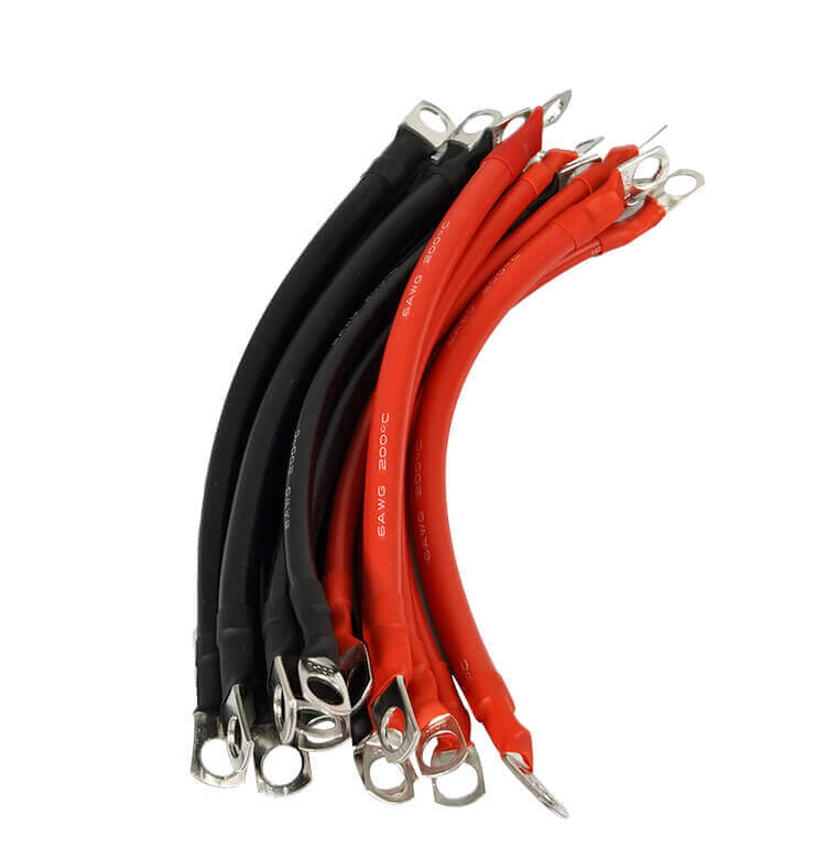
An EV energy storage wiring harness may look like a collection of cables, terminals, connectors, and protective sleeves, but every component affects vehicle safety. Continuous vibration, temperature cycling, moisture, electromagnetic noise, and current loads reaching 200A–400A can expose weaknesses that remain invisible during a basic continuity test.
A damaged energy storage wiring harness can cause excessive voltage drop, unstable BMS communication, reduced power output, insulation failure, or localized overheating. Understanding how these failures develop is the first step toward designing a safer new energy wiring harness.
Why Wiring Harness Reliability Matters in EV Systems
Power and signal circuits face different stresses
An automotive wiring harness may contain high-current power conductors, low-voltage control wires, sensor circuits, and communication lines. Power cables must carry current without unacceptable heat or voltage loss. Signal circuits require stable transmission and protection from electromagnetic interference.
Limited installation space creates additional mechanical pressure. Tight bends, unsupported cable weight, sharp metal edges, and nearby heat sources can turn a suitable cable into an unreliable assembly.
Failures often begin at connection points
A mismatched terminal, incomplete crimp, oxidized contact surface, or loose connector can create concentrated resistance. Under high current, this resistance becomes a hot spot. Heat then accelerates insulation aging, connector deformation, and contact deterioration.
Six Common EV Energy Storage Wiring Harness Failures and Solutions
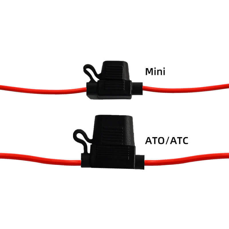
The six issues below show how heat, vibration, electrical load, electromagnetic noise, moisture, and installation constraints affect harness reliability. Each failure is followed immediately by the design and validation measures that address it.
Thermal Aging and Insulation Cracking
Repeated heating and cooling cause conductors, insulation, terminals, and connector housings to expand at different rates. An unsuitable jacket may gradually harden, shrink, crack, or separate near a terminal.
Common warning signs include:
- brittle or discolored insulation;
- cracks near bends and connector exits;
- faults that appear only in hot or cold conditions;
- declining insulation resistance;
- softened jackets near high-current connections.
Once insulation integrity is lost, the conductor becomes vulnerable to moisture, abrasion, leakage current, and short circuits.
Solution 1 : Match Insulation Materials to the Environment
Material selection should consider ambient temperature, conductor temperature rise, flexibility, abrasion, oil exposure, moisture, and expected service life.
PVC can suit many general-purpose applications, while TPE or silicone may provide greater flexibility or temperature performance in specific environments. PE, rubber, braided sleeves, and heat-shrink tubing can provide additional protection where required.
Huajunxin works with PVC, PE, silicone, rubber, braided wire, shielded wire, and multi-core wire. This material range allows construction to be matched to the application instead of applying one insulation system to every automotive wiring harness.
Vibration, Loose Terminals, and Broken Conductors
Vehicle vibration repeatedly loads terminals, crimps, fixing points, and unsupported bends. A loose terminal may maintain contact while the vehicle is stationary, then disconnect briefly on rough roads.
Internal strand damage can also remain hidden beneath an intact jacket. Typical symptoms include:
- intermittent power loss;
- unstable sensor readings;
- BMS communication warnings;
- abnormal contact resistance;
- faults that disappear during workshop inspection.
Excessive movement can also cause the harness to rub against brackets, body panels, or nearby components until the insulation wears through.
Solution 2 : Control Movement with Terminals and Strain Relief
Vibration resistance should be built into the mechanical structure through:
- positive-locking terminals;
- secure connector retention;
- flexible stranded copper conductors;
- strain relief at cable exits;
- suitable clamp spacing;
- controlled bending radii;
- protection from sharp edges and moving parts.
The objective is to limit damaging movement without creating rigid stress points. Excessive clamping can be as harmful as insufficient support.
High-Current Heating and Excessive Voltage Drop
High-current faults are among the most dangerous problems in an EV energy storage wiring harness. As current rises, even a small increase in conductor or contact resistance produces significantly more heat.
A 200A–400A circuit becomes vulnerable when:
- the conductor cross-section is too small;
- the cable run is unnecessarily long;
- multiple cables are tightly bundled;
- ambient temperature is high;
- terminal contact resistance is excessive;
- peak current is ignored during cable selection.
Warning signs include unusually warm cable jackets, connector discoloration, reduced power output, a burning odor, softened insulation, and excessive voltage drop.
Solution 3 : Size the Complete High-Current Path
Wire gauge should be selected from the complete operating condition rather than nominal current alone. Engineering inputs should include:
- continuous and peak current;
- peak-current duration;
- cable length;
- allowable voltage drop;
- ambient temperature;
- bundle size and ventilation;
- conductor temperature limit;
- connector and terminal capacity.
Huajunxin’s published high-current battery connection cable includes 10AWG, 8AWG, 6AWG, and 4AWG configurations, customizable lengths, several terminal-hole sizes, and PVC, TPE, or silicone jackets. The correct configuration still depends on the application’s current, installation space, and thermal environment.
Crimp quality must be evaluated together with conductor size. Crimp height, compression, conductor insertion, terminal material, and contact-surface condition all affect resistance. A large cable cannot compensate for an unstable termination.
Electromagnetic Interference and BMS Errors
High-current switching circuits generate electromagnetic noise. Long parallel routing between power cables and low-voltage signal lines can create unwanted coupling.
An affected new energy wiring harness may produce:
- unstable BMS communication;
- incorrect sensor readings;
- CAN communication errors;
- unexplained dashboard warnings;
- faults that appear during charging, acceleration, or heavy load.
Poor shield termination or grounding may make interference more severe. A cable can pass a static electrical test while still producing communication faults during real vehicle operation.
Solution 4 : Separate Power and Signal Circuits
Power cables and sensitive signal lines should be separated wherever possible. Unnecessary parallel runs should be avoided, especially near switching devices, inverters, and other high-current components.
Depending on the circuit, protection may include:
- twisted conductors;
- braided or foil shielding;
- separate routing channels;
- controlled shield termination;
- an application-specific grounding strategy.
Huajunxin produces shielded and multi-core cable constructions that can support customized signal and power routing. Final suitability should be verified through system-level EMC testing under realistic load conditions.
Moisture Ingress and Terminal Corrosion
Moisture can enter through damaged insulation, connector interfaces, cable exits, or incompletely sealed crimps. Terminal oxidation then increases contact resistance, creating additional heat and accelerating seal degradation.
Solution 5 : Build Waterproofing into the Complete Assembly
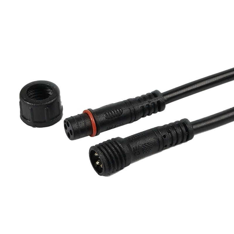
Waterproof performance depends on more than the connector. Cable material, seals, terminal joints, heat-shrink tubing, overmolding, strain relief, and routing must operate as one system.
The Huajunxin waterproof harness case used an IP68 structure and completed 10 million bending cycles at a bending radius equal to ten times the cable diameter without conductor breakage. This result connects sealing performance with flex life and mechanical durability.
Where relevant, validation should include:
- water-ingress testing;
- humidity exposure;
- temperature cycling;
- salt-spray testing;
- connector-seal inspection;
- repeated bending.
Poor Customization and Routing Fit
A standard energy storage wiring harness cannot fit every vehicle platform. Connector types, cable lengths, terminal orientation, fixing points, current loads, and available installation space vary between projects.
Poor fit can cause:
- excessive tension at connector exits;
- tight bends and conductor fatigue;
- contact with sharp brackets;
- unsupported cable weight;
- unnecessary loops and vibration;
- installation rework;
- delayed prototype validation.
Fast vehicle-model updates also create procurement pressure. High minimum order quantities, slow sampling, and delayed responses to drawing changes can prevent a project from keeping pace with development schedules.
Solution 6 : Customize from Drawings and Application Data
A custom new energy wiring harness should begin with confirmed technical inputs:
- operating voltage;
- continuous and peak current;
- cable length and wire gauge;
- connector and terminal specifications;
- installation drawing;
- temperature and environmental exposure;
- shielding and waterproofing requirements;
- prototype and production quantities.
Huajunxin supports customization of cable length, wire gauge, connector type, terminal size, and sheath material across published cable products. Drawing- or sample-based development can identify routing and assembly problems before mass production.
Rapid prototyping and small-batch validation are especially valuable when vehicle platforms change frequently.
Validation Before Mass Production
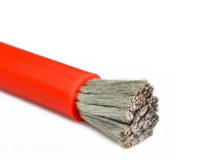
A production-ready energy storage wiring harness should pass tests appropriate to the intended application.
Electrical and thermal validation may include:
- continuity;
- contact resistance;
- voltage drop under load;
- insulation resistance;
- dielectric withstand;
- full-load temperature rise;
Mechanical and environmental validation may include:
- terminal pull force;
- connector retention;
- vibration and mechanical shock;
- repeated bending and abrasion;
- temperature cycling;
- humidity and water ingress.
A room-temperature continuity test cannot prove stable operation under high current, vibration, moisture, and thermal cycling.
Conclusion
A reliable EV energy storage wiring harness is an engineered electrical and mechanical system rather than a bundle of wires. Thermal aging, vibration, high-current heating, electromagnetic interference, moisture corrosion, and poor customization often interact.
A loose terminal can generate heat. Heat can damage a seal. The presence of moisture can increase resistance, while an increased resistance creates even more heat. Reliability will depend on designing the conductor, insulation, terminal, shielding, sealing, routing, and testing according to the real application.
Huajunxin combines configurable materials, terminal processing, shielded cable construction, waterproof development, and custom cable assembly options to support application-specific projects.
Contact us to discuss a custom wiring harness based on current, voltage, connector, material, environment, drawing, and quantity requirements.
FAQ
Q: What causes an EV energy storage wiring harness to overheat?
A: Possible reasons for voltage drop may be small conductor size, high load, excessive cable length, poor crimping, loose connections, corroded parts, tight packing, and inadequate heat dissipation. Voltage-drop test, contact resistance test, and temperature rise under full load should be performed during diagnosis.
Q: How should wire gauge be selected for an energy storage wiring harness?
A: Wire gauge should be selected based on continuous current, peak-current duration, cable length, ambient temperature, bundle size, acceptable voltage drop, and terminal capacity. A nominal ampacity table alone is insufficient.
Q: Can Huajunxin customize an EV energy storage wiring harness from a drawing or sample?
A: Custom development can be evaluated from drawings or samples after confirming voltage, current, cable length, wire gauge, connector type, terminal size, sheath material, environmental requirements, testing needs, and production quantity.
 Address: A203, Building 3, Xinsheng Community, Longgang Subdistrict, Longgang District, Shenzhen, Guangdong Province


